Fuse Layout Chevrolet Trax 2013-2017

Cigar lighter (power outlet) fuses in the Chevrolet Trax are the fuses №21 (AC Accessory Power Outlet), №22 (Cigar Lighter/DC Accessory Power Outlet) in the Instrument panel fuse box.
Table of Contents
Instrument Panel Fuse Box
Fuse box location
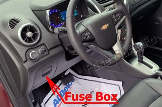
It is located on the underside of the driver side instrument panel, behind the storage compartment to the left of the steering wheel.
Fuse box diagram
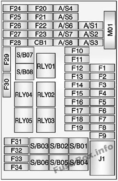 Assignment of the fuses and relays in the Instrument Panel
| № | Usage |
|---|---|
| Mini Fuses | |
| 1 | Body Control Module 1 |
| 2 | Body Control Module 2 |
| 3 | Body Control Module 3 |
| 4 | Body Control Module 4 |
| 5 | Body Control Module 5 |
| 6 | Body Control Module 6 |
| 7 | Body Control Module 7 |
| 8 | Body Control Module 8 |
| 9 | Discrete Logic Ignition Switch |
| 10 | Sensing Diagnostic Module Battery |
| 11 | Data Link Connector |
| 12 | Heater, Ventilation, and Air Conditioning MDL |
| 13 | Liftgate Relay |
| 14 | UPA Module |
| 15 | Inside Rearview Mirror |
| 16 | Not Used |
| 17 | Driver Power Window Switch |
| 18 | Rain Sensor |
| 19 | Body Control Module Regulated Voltage Control |
| 20 | Steering Wheel Switch Backlighting |
| 21 | A/C Accessory Power Outlet |
| 22 | Cigar Lighter/DC Accessory Power Outlet |
| 23 | Spare |
| 24 | Spare |
| 25 | Spare |
| 26 | Automatic Occupant Sensing Display SDM RC |
| 27 | IPC/Compass Module |
| 28 | Headlamp Switch/ DC Converter/Clutch Switch |
| 29 | Spare |
| 30 | Spare |
| 31 | IPC Battery |
| 32 | Radio/Chime |
| 33 | Display |
| 34 | OnStar (If Equipped)/VLBS |
| S/B Fuses | |
| 1 | PTC 1 |
| 2 | PTC 2 |
| 3 | Power Window Motor Front |
| 4 | Power Window Motor Rear |
| 5 | Logistic Mode Relay |
| 6 | Spare |
| 7 | Front Power Windows |
| 8 | Rear Power Windows |
| Circuit Breaker | |
| CB1 | Spare |
| Midi Fuse | |
| M01 | PTC |
| Relays | |
| RLY01 | Accessory/Retained Accessory Power |
| RLY02 | Liftgate |
| RLY03 | Spare |
| RLY04 | Blower Relay |
| RLY05 | Logistic Mode |
| Main Connector | |
| J1 | IEC MAIN PWR CONNECTOR |
Engine Compartment Fuse Box
Fuse box location
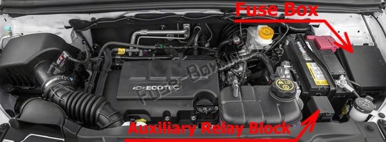
It is located in the engine compartment on the driver’s side.
Fuse box diagram
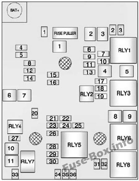 Assignment of the fuses and relays in the Engine Compartment
| № | Usage |
|---|---|
| Mini Fuses | |
| 1 | Sunroof |
| 2 | Outside Rearview Mirror Switch |
| 3 | Canister Vent Solenoid (1 4L Only) |
| 4 | Not Used |
| 5 | Electronic Brake Control Module Valve |
| 6 | 2013: IBS |
| 7 | Not Used |
| 8 | Transmission Control Module Battery |
| 9 | Not Used |
| 10 | Fuel System Control Module R/C (1.4L Only)/Headlamp Leveling |
| 11 | Rear Wiper |
| 12 | Rear Window Defogger |
| 13 | Not Used |
| 14 | Outside Rearview Mirror Heater |
| 15 | Fuel System Control Module Battery (1.4L Only) |
| 16 | Heated Seat Module |
| 17 | Transmission Control Module R/C |
| 18 | Lngine Control Module R/C |
| 19 | Fuel Pump (1.8L Only) |
| 20 | Not Used |
| 21 | Fan Relay (Auxiliary Fuse Block - 1.4LV Fan 3 Relay 85 (1.8L) |
| 22 | Cold Start Pump (1.8L Only) |
| 23 | Ignition Coil/lnjectors |
| 24 | Washer Pump |
| 25 | Not Used |
| 26 | Canister Purge Solenoid/Water Valve Solenoid/ Oxygen Sensors -Pre and Post/Turbo Wastegate Solenoid (1.4L)/Turbo Bypass Solenoid (1.4LV IMTV Solenoid (1.8L) |
| 27 | Not Used |
| 28 | 2013: Gasoline: NOT USED Diesel: ECM PT IGN-3 |
| 29 | Engine Control Module Powertrain Ignition 1/Ignition 2 |
| 30 | Mass Air How Sensor Diesel: O2 SENSOR |
| 31 | Left High-Beam Headlamp |
| 32 | Right High-Beam Headlamp |
| 33 | Engine Control Module Battery |
| 34 | Horn |
| 35 | Air Conditioning Compressor Clutch |
| 36 | Front Fog Lamps |
| J-Case Fuses | |
| 1 | Electronic Brake Control Module Pump |
| 2 | Front Wiper |
| 3 | Blower Motor |
| 4 | IEC A/C |
| 5 | Not Used |
| 6 | 2013: Gasoline: NOT USED Diesel: FUEL HEATER |
| 7 | Not Used |
| 8 | Cooling Fan Low/ Mid (1.4L)/Cooling Fan Low (1.8L) |
| 9 | Cooling Fan High |
| 10 | 2013: Gasoline: EVP Diesel: GLOW PLUG |
| 11 | Starter Solenoid |
| U-Micro Relays | |
| RLY2 | Fuel Pump (1.8L Only) |
| RLY4 | Spare |
| HC-Micro Relays | |
| RLY7 | Starter |
| Mini Relays | |
| RLY1 | Run Crank |
| RLY3 | Cooling Fan Mid (1.4L Only) |
| RLY5 | Powertrain Relay |
| RLY8 | Cooling Fan Low |
| HC-Mini Relays | |
| RLY6 | Cooling Fan High |
Auxiliary Relay Block
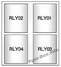 Auxiliary Relay Block
| Relays | Usage |
|---|---|
| RLY01 | Electric Vacuum Pump |
| RLY02 | Cooling Han Control 1 |
| RLY03 | Cooling Fan Control 2 |
| RLY04 | Trailer (1.4L Only) |
Rear Compartment Fuse Box
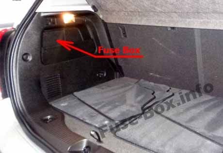
Fuse box location
It is located behind a cover on the left side of the rear compartment.
Fuse box diagram
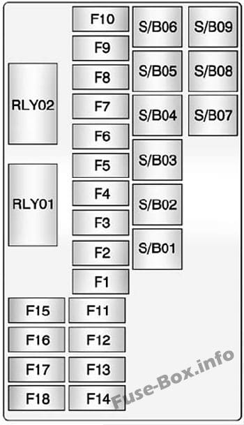 Assignment of the fuses and relays in the Luggage Compartment
| № | Usage |
|---|---|
| Mini Fuses | |
| 1 | Driver Seat Power Lumbar Switch |
| 2 | Passenger Seat Power Lumbar Switch |
| 3 | Amplifier |
| 4 | Trailer Socket |
| 5 | All-Wheel Drive Module |
| 6 | Automatic Occupant Sensing Module |
| 7 | Spare/LPG Module Battery |
| 8 | Trailer Parking Lamps |
| 9 | Spare |
| 10 | Spare/Side Blind Zone Alert Module |
| 11 | Trailer Module |
| 12 | Nav Dock |
| 13 | Heated Steering Wheel |
| 14 | Trailer Socket |
| 15 | EVP Switch |
| 16 | Water In Fuel Sensor |
| 17 | Inside Rearview Mirror/Regulated Voltage Control |
| 18 | Spare/LPG Module Run/Crank |
| S/B Fuses | |
| 1 | Driver Power Seat Switch/Memory Module |
| 2 | Passenger Power Seat Switch |
| 3 | Trailer Module |
| 4 | A/C-D/C Inverter |
| 5 | Battery |
| 6 | Headlamp Washer |
| 7 | Spare |
| 8 | Spare |
| 9 | Spare |
| Relays | |
| 1 | Ignition Relay |
| 2 | Run Relay |
